中文  /  EN

首页 > Products > Torque limiter

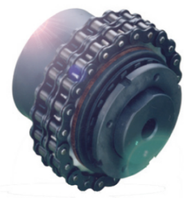
MF Friction torque limiter

产品型号:

标准编号:
联轴器类型:
公称转矩:
轴孔:
外形尺寸:
孔径:
重量:
长度:
外径:
是否提供加工定制:

产品描述
参数详情

Simple and economical friction type torque limiter

Suitable for working in dusty conditions, no need for speed adjustment between gearbox and output equipment

No noise and vibration when overloaded

Rotation two-way protection

Non-asbestos friction disc

It is adjusted by the locking ring, the torque setting is simple and accurate

Innovative dimensional calibration system, which can calibrate the equipment instantaneously


On demand

Equipped with a complete transmission gear, all turned and assembled (sprocket, pulley, gear pair)

Various friction plates suitable for specific purposes

Multiple connection methods such as keyway, spline and expansion sleeve can be provided

The surface layer is treated with anti-corrosion to meet special requirements


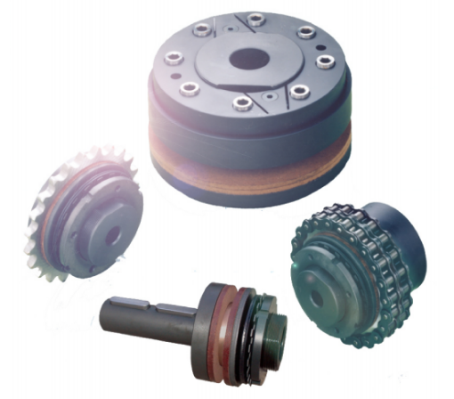
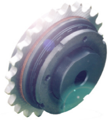
The sprocket, pulley or other transmission components in the friction torque limiter are installed between the two sliding plates. When the torque is reached, it can ensure continuous transmission without damaging the components. The characteristics of the device are: simple structure, low price, suitable for use in environments where torque accuracy is not very high.


Main  application

Forming machinery

Conveying machinery

Fan  

Agricultural machinery, woodworking machinery


Advantages and features

Protect the motor gearbox in an accidental collision

In case of overload, the conveyor line can be stopped in time

Protect the motor and blade when the blade is stuck

Protect the gearbox in the case of short-term blockage of the product


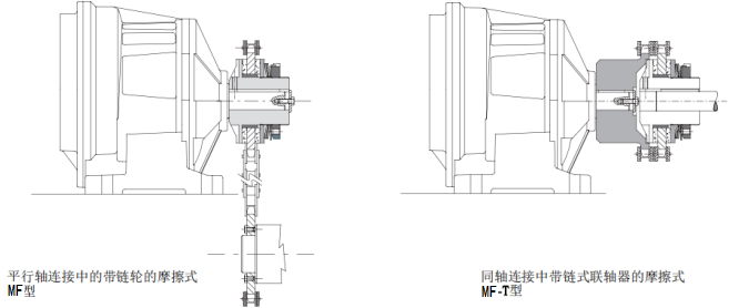
MF:Basic model of parallel shaft drive, with sprocket, gear pair or pulley

1-23000Nm

Maximum hole  140mm


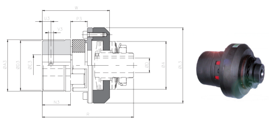
MF-T:Coaxial connection, simple and economical

1-23000Nm

Maximum hole  160mm


MF-G:Coaxial connection, with elastic coupling, large compensation range

1-23000Nm

Maximum hole  160mm

Application example


Dimensions  

size

A

B

h7

DH7

F

G

G1

L

M

M1

P*

Prefabricated hole

Max.

Min.

Max.

Max.

0

25

14

-

8

22

1

3

-

5

26

-

M3*

1

38

24

-

12

32

1

5

21

8

33

46

M3

2

50

36

-

20

44

1

6

26

10

35

57.5

M4

3

70

45

-

25

63

1

10

40

15

55

85

M6

4

90

60

-

38

82

3

12

46

16

60

95

M6

5

115

72

18

45

104

5

16

58

18

70

113

M6

6

140

85

24

55

130

8

19

69

20

80

136

M8

7

170

98

28

65

158

10

22

78

22.5

95

153.5

M8

8

205

120

38

80

193

18

26

90

27

110

174

-

9

240

145

50

100

230

18

29

99

27

116

186

-

10

300

175

60

120

287

21

33

113

29

123

203

-

11

340

205

60

130

325

23

33

113

41

158

238

-

12

400

230

60

140

388

23

35

119

46

167

251

-


Performance parameter 

Size

Torque(Nm)

inertia

10-3 kg㎡

Max.speed(rpm)

Mass(kg)

T0

T1

T2

T3

MF

.../ML

0

-

1-8

2-12

2-20

0,003

10000

0,1

-

1

-

1-14

8-22

15-34

0,022

10000

0,2

0,3

2

2-12

4-40

17-70

23-100

0,075

7600

0,4

0,5

3

6-18

17-60

34-120

60-210

0,390

5450

1,1

1,4

4

13-105

74-140

90-280

185-450

1,167

4250

2,2

2,8

5

65-280

120-360

207-700

210-950

3,809

3350

3,7

4,8

6

-

180-550

260-950

390-1200

9,982

2750

6,6

8,5

7

-

160-700

300-1450

1000-2600

23,943

2250

10,9

13,5

8

300-1200

500-2400

1000-4800

-

75,088

1900

20,1

24,5

9

500-2000

1000-4000

2000-8000

-

152,946

1600

30,9

37,8

10

800-3500

1500-7000

3000-14000

-

380,357

1300

49,1

60,8

11

1000-4500

2000-9000

4000-18000

-

869,290

1200

85,5

102,5

12

1500-5000

3000-11000

5000-23000

-

1830,092

1000

124,5

147,7


Description

P*: The size is 00.25, the flat head screw is located on the nut side, not on the flange side

The weight is related to the torque limiter with pre-made holes (MF), and the inertia refers to the maximum diameter of the hole


Dimensions  

size

A

DH7

F

M

R

A3

D3

E3H7

N3

U3

V3

Prefabricated hole

Max

Prefabricated hole     Max

0

25

-

8

22

26

39

45

23

8

12

9

4

M3

1

38

-

12

32

33

58

57

37

10

20

20

5

M3

2

50

-

20

44

35

58

75

50

12

28

19

8

M4

3

70

-

25

63

55

87

101

70

16

38

29

12

M6

4

90

-

38

82

60

102

126

89

20

55

38

12

M6

5

115

18

45

104

70

131

159

112

20

70

56.5

15

M8

6

140

24

55

130

80

145

184

130

28

80

59.5

15

M8

7

170

28

65

158

95

189

215

130

30

80

88

15

M8

8

205

38

80

193

110

218

291

150

38

90

103

25

M10

9

240

50

100

230

116

245

310

170

50

110

124

25

M10

10

300

60

120

287

123

284

374

200

50

140

147

30

M12

11

340

60

130

325

158

329

423

210

60

150

165

30

M12

12

400

60

140

388

167

364

471

240

60

160

191

30

M16

Performance parameter 

size

Torque(Nm)

compensate

Max.speed

(rpm)

Mass

(kg)

T0

T1

T2

T3

Angular α(°)

Axial Xmm

Radial Kmm

0

-

1-8

2-12

2-20

1,50

0,20

5000

0,2

1

-

1-14

8-22

15-34

1,50

0,20

5000

0,6

2

2-12

4-40

17-70

23-100

1,50

0,20

3800

1,1

3

6-18

17-60

34-120

60-210

2,40

0,25

2800

2,8

4

13-105

74-140

90-280

185-450

3,20

0,30

2200

5,9

5

65-280

120-360

207-700

210-950

4,50

0,35

1800

11,1

6

-

180-550

260-950

390-1200

4,80

0,40

1500

20,3

7

-

160-700

300-1450

1000-2600

4,80

0,40

1300

31

8

300-1200

500-2400

1000-4800

-

6,30

0,50

1000

54,6

9

500-2000

1000-4000

2000-8000

-

6,30

0,50

900

76,7

10

800-3500

1500-7000

3000-14000

-

6,80

0,55

700

125,5

11

1000-4500

2000-9000

4000-18000

-

6,80

0,55

600

180

12

1500-5000

3000-11000

5000-23000

-

6,80

0,55

550

260

Description


▪ The modified data is related to the entire array (MF-T)

▪ The quality is related to how large the inner hole is (MF-T)


MF-G  claw coupling model 


Dimensions  

Size

A

DH7

F

M

R

A3

L3

E3H7

N3

U3

V3

Prefabricated hole

Max.

Prefabricated hole

Max.

0

25

-

8

22

26

56

30

43

-

16

11

5

M4

1

38

-

12

32

33

84.5

40

58

-

25

25

10

M4

2

50

-

20

44

35

58

55

74

-

35

30

10

M5

3

70

-

25

63

55

87

80

107

-

48

45

15

M8

4

90

-

38

82

60

102

95

132

-

55

50

20

M8

5

115

18

45

104

70

131

120

164

-

74

65

20

M10

6

140

24

55

130

80

145

160

208

28

95

85

25

M10

7

170

28

65

158

95

189

200

246

30

110

100

30

M12

8

205

38

80

193

110

218

225

285

38

115

110

30

M12

9

240

50

100

230

116

245

255

330

50

125

120

33

M16


Performance parameter 

Size

Torque(Nm)

compensation

Max.speed

(rpm)

Mass

(kg)

T0

T1

T2

T3

Angle α(°)

Axial X(mm)

Radial K(mm)

0

-

1-8

2-12

2-20

0.54°

1

0.09

10000

0.2

1

-

1-14

8-22

15-34

1

0.20

10000

0.4

2

2-12

4-40

17-70

23-100

1

0.22

7600

0.8

3

6-18

17-60

34-120

60-210

1.4

0.28

5450

3.3

4

13-105

74-140

90-280

185-450

1.6

0.32

4250

5.4

5

65-280

120-360

207-700

210-950

1.8

0.38

3350

10.3

6

-

180-550

260-950

390-1200

2.5

0.48

2750

21.1

7

-

160-700

300-1450

1000-2600

2.8

0.50

2250

36.3

8

300-1200

500-2400

1000-4800

-

3.0

0.52

1900

59.9

9

500-2000

1000-4000

2000-8000

-

3.2

0.55

1600

87.7